To ensure the best performance and prolong the durability of the antenna, there are three principles to be implemented
The antenna by VSAT antenna manufacturers should be installed on the highest level, on the top deck of all types of ships. It shall be kept away from other obstructions such as center mast, chimney, light stand, etc., and away from onboard communication equipment such as radar, satellite TV, walkie-talkie, etc.
If the main course of the ship is north-south, standing on the ship and facing the bow, the right front corner of the highest floor is the best installation position. The left rear corner is the second choice (if the chimney is at the rear part of the ship, do not install it at the rear part). For the east-west direction, standing on the ship and facing the bow, the front left corner of the highest floor is the best installation position. The rear right corner is the second choice (if the chimney is at the rear part of the ship, do not install it at the rear part). For ships with irregular courses, the installation position is determined on-site according to the actual situation of the hull, and kept away from the obstruction. No matter which corner it is installed, it should be as close as possible to the corner and the two perpendicular sides. In principle, the distance between the center point of the antenna column and the two perpendicular sides is 60cm± 5cm.

Fig. 1 Antenna installation position
The best installation location of the antenna is based on the position of the top mast and the main course of the ship.
The antenna shall be installed in position 1, if the ship is sailing from west to east.
The antenna shall be installed in position 2, if the ship is sailing from south to north.
The antenna shall be installed at position 3, if the ship is sailing from east to west.
The antenna shall be installed at position 4, if the ship is sailing from north to south.
Main course | Best installation location | Remark |
South-north | 2&4, 3 meters away from mast | Away from the chimney, communication equipment and other obstruction |
East-west | 1&3, 3 meters away from mast |
The installed antenna bracket and antenna head should be kept away from other items on the ship as much as possible. The installation position of the antenna and the course of the ship may cause signal blockage.
The installation and fixing of the antenna bracket, the antenna head and the cable routing should be based on firmness and durability. The antenna support, bracket, antenna head must be placed in position according to the installation principles.
The parts that need to be welded, such as the bracket, the antenna, angle iron, and so on, must be welded from the column → bracket head → angle iron. The column and the hull, the column and the bracket head must be fully welded. The angle iron and the hull must be welded firmly. After the welding is completed, clean the welding slag and check whether there is any cold solder joint.
The screw must be tightened in place with a wrench. There are 6 fixing screws for the VS series antenna, check if there is anything missing.
The joints of the cable must be firmly connected and in good contact. They should be tested artificially pulling with a certain force and without loosened.
The direction of the cable harness must be scientifically considered. It should be placed along the edge of the ship, railings, and pipelines. It should be concealed in the corresponding parts of the hull without bending, and not be easy to touch.
After installation, the antenna cover and bracket should be wiped clean, and the wrapping film on the antenna cover should be removed. The extra cables should be bundled neatly and placed in a hidden place where they will not be touched. The items left on the site after installation should be cleaned up.
In order to ensure the safety and reliable operation of the VSAT terminal equipment, there must be voltage-stabilized power supply and functional batteries.
The input of the voltage-stabilized power supply must be connected to the battery, and it is strictly forbidden to connect the voltage-stabilized power supply to the charger, otherwise, while switching, the end user will not be able to access the internet normally, and the equipment will be damaged long-term basis.
2.2.1 Antenna installation location selection specifications
Before installation, the type of the ship need be confirmed and the actual situation of the deck need be checked. The installation position of the antenna should be at least 3 meters far away from the mast, and it should be away from the light frame, lamp tube, chimney, other communication and navigation equipment, etc. The installation location should also avoid the working areas.
2.2.2 Antenna bracket welding specifications
It is highly recommended to use the whole set of BIRDSAT original bracket. The upper ends of the three angle irons are fixed to the bracket heads, and the lower ends are welded to the hull to ensure the welding firmly.
All welding points must be well and fully welded to ensure that the brackets are welded firmly.The welding parts need to be sprayed with anti-rust paint. While welding, pay attention to welding safety and keep non-welding personnel away from the welding operation area.
2.2.3 Antenna installation specifications
When the antenna prodcued by BIRDSAT VSAT company is loaded onto the ship, pay attention to the safety of personnel and equipment. Before the antenna bag is lifted to the head of the stand, the covering on the antenna bag, such as wrapping film and canvas cover should be removed, and the surface of the antenna bag should be cleaned. When the antenna package is transported to the stand, at least 3 people should carry it. When the antenna package is fixed to the bracket head, it must be fully tightened with the original bolts. The outdoor cable connector must be tightened with a special tool (motor tightening pliers) to ensure that the connector is in good contact. The cable must be fixed at 10cm from the connector, and a waterproof baffle must be installed at the same time. The outdoor cables should be placed close to the bracket head, the column and the inner side of the angle iron. The excess cables should be straightened out, bundled and fixed.
2.2.4 Cable installation specifications
All cable connectors must be fixed with saddle clips within 10cm of the connector, and the cables should be straightened to ensure that the connectors are not stressed or fallen off. When selecting an outdoor cable, select the appropriate cable length according to the model of the ship and the installation location of the antenna. When the outdoor cable is routed, 2 persons cooperate with the pulling operation. During operation, the cable connector must be protected, and don’t pull it with brute force. After the outdoor cable routed to the cabin, a U-shaped waterproof pocket must be made to prevent water from flowing into the cable and damaging the equipment.
a. Carry out the antenna and place it on the stand, and adjust the position of the antenna package (the cable outlet faces the stern).
b. Remove the canvas bag of the antenna.
c. Use M12*30 screws to fix the 6 screws at the bottom of the antenna on the bracket (the spring washer and the flat washer need to be placed in sequence), and tighten them with a No. 19 wrench.
d. Thread the outdoor cable (ANT cable).
Take the outdoor cable (ANT cable) to the top deck of the ship, and wrap the cable connector that will be put indoors with a grommet. Route the outdoor cable (ANT cable) along the corners of the boat as much as possible according to the antenna installation position, and straighten the cable. Bundle the connector of the outdoor cable (ANT cable) which has been put into the room with other cables at the threading port, and the coordinate person pulls it slowly from indoor to route it into the room. Remove the protective cover and put it away for later use.
e. Connect the outdoor cable (ANT cable) at the bottom of the antenna and ensure that the connector is firmly connected.
f. Place the outdoor cable (ANT cable) along the groove of the bottom of the antenna, fasten the water baffle to the bottom of the antenna, adjust the position of the water baffle and the outdoor cable (ANT cable), and then use 4 M5*16 screws to fix it.
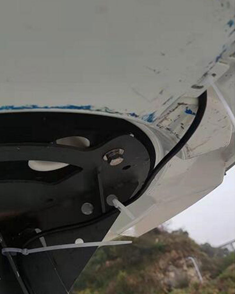
g. The cable coming out of the water baffle should be fixed to the head of the bracket with a cable tie.
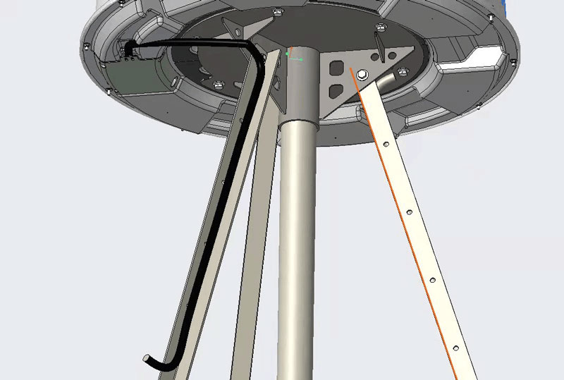
h. Tighten the outdoor cable (ANT cable) to the angle iron and handrail. Be careful not to bend the cable excessively and ensure that the cable is smooth without crease.

Fig. 2 Tighten the outdoor cable (ANT cable) to the angle iron and handrail

Fig. 3 Picture of cable tightening
i. Fasten the remaining combination cable along the angle iron with cable ties on the inner side of the angle iron.
j. After passing the cables from the outdoors to the indoors, install the indoor unit.
Recommending Reading:
Related Products: